
3-Wire RTD Calculation: Complete Guide for Accurate Temperature Measurement
Article Outline
- H1: 3-Wire RTD Calculation: Complete Guide
- H2: What is an RTD?
- H3: Basic Working Principle of RTD
- H3: Why Resistance Matters in Temperature Measurement
- H2: Understanding RTD Wiring Configurations
- H3: 2-Wire vs 3-Wire vs 4-Wire RTD
- H3: Why 3-Wire RTD is Most Common
- H2: What is a 3-Wire RTD?
- H3: Structure of a 3-Wire RTD
- H3: Role of Each Wire
- H2: Importance of 3-Wire RTD Calculation
- H3: Problem of Lead Wire Resistance
- H3: How 3-Wire RTD Solves It
- H2: 3-Wire RTD Calculation Formula
- H3: Voltage-Based Calculation
- H3: Resistance-Based Calculation
- H2: Step-by-Step 3-Wire RTD Calculation Example
- H3: Example with Ohm’s Law
- H3: Practical Industrial Example
- H2: Assumptions in 3-Wire RTD Calculation
- H3: Equal Wire Resistance Condition
- H3: Impact of Unequal Resistance
- H2: Accuracy and Limitations
- H3: Sources of Error
- H3: How to Minimize Errors
- H2: Applications of 3-Wire RTD
- H3: Industrial Uses
- H3: Real-World Examples
- H2: Advantages and Disadvantages
- H3: Benefits of 3-Wire RTD
- H3: Drawbacks Compared to 4-Wire RTD
- H2: Conclusion
- H2: FAQs
- H2: What is an RTD?
3-Wire RTD Calculation: Complete Guide for Accurate Temperature Measurement
What is an RTD?
Basic Working Principle of RTD
A Resistance Temperature Detector (RTD) is one of the most reliable sensors used to measure temperature in industrial and scientific applications. At its core, an RTD operates on a simple yet powerful principle: the electrical resistance of a metal changes with temperature. When temperature increases, resistance increases in a predictable and repeatable manner. This relationship allows engineers to measure temperature indirectly by measuring resistance.
Most RTDs are made using platinum because of its stable and linear resistance-temperature relationship. You might have heard of PT100, which means the sensor has a resistance of 100 ohms at 0°C. As temperature rises, the resistance increases proportionally. This predictable behavior is what makes RTDs extremely accurate compared to other sensors like thermocouples.
But here’s where things get interesting. The RTD itself is not the only resistance in the system. The wires connecting the RTD to the measuring instrument also have resistance. That additional resistance can distort the measurement if not properly compensated. This is exactly why different wiring configurations exist, including the widely used 3-wire RTD system.
Why Resistance Matters in Temperature Measurement
Think of resistance like friction in a pipe carrying water. If you only care about the flow inside the pipe but ignore the friction in the connecting hoses, your measurement becomes inaccurate. Similarly, when measuring temperature using RTDs, the resistance of connecting wires adds unwanted “noise” to the actual reading.
In a simple 2-wire RTD, the total measured resistance includes both the RTD element and the lead wires. This creates an error that increases with wire length. Even a small resistance in the wire can cause a noticeable temperature deviation, especially in precision systems.
That’s why engineers developed improved wiring methods like the 3-wire RTD configuration, which significantly reduces this error by compensating for lead resistance. The calculation behind this compensation is what makes the 3-wire system so effective and widely adopted.
Understanding RTD Wiring Configurations
2-Wire vs 3-Wire vs 4-Wire RTD
RTDs can be connected in three main configurations: 2-wire, 3-wire, and 4-wire. Each configuration offers a different level of accuracy and complexity.
- 2-wire RTD: Simplest and cheapest, but least accurate because it includes full lead resistance in the measurement.
- 3-wire RTD: A balance between cost and accuracy; compensates for most lead resistance errors.
- 4-wire RTD: Most accurate; completely eliminates lead resistance error but requires more wiring.
In industrial environments, the 3-wire RTD is often the preferred choice because it delivers high accuracy without the complexity and cost of a 4-wire system. According to industry sources, it can reduce lead resistance error by approximately 50% compared to a 2-wire system .
Why 3-Wire RTD is Most Common
The popularity of the 3-wire RTD comes from its smart design. It uses an additional wire to compensate for resistance without needing a full four-wire setup. This makes it ideal for long-distance temperature measurements in industries like oil & gas, power plants, and manufacturing.
Imagine you’re trying to weigh something using a scale that has extra weight added unknowingly. The third wire in a 3-wire RTD acts like a correction mechanism that removes that extra weight from the measurement. It’s not perfect, but it’s highly effective under the right conditions.
What is a 3-Wire RTD?
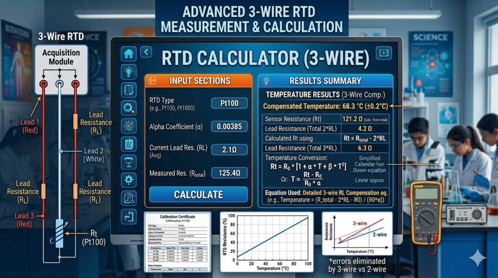
Structure of a 3-Wire RTD
A 3-wire RTD consists of three leads connected to the sensing element. Typically, two wires are connected to one side of the RTD element, and the third wire is connected to the other side. This configuration allows the measurement system to compare resistances and cancel out the effect of lead wires.
Inside the measurement circuit, the RTD is often part of a Wheatstone bridge or similar setup. This arrangement allows precise measurement of resistance changes while minimizing errors caused by external factors.
Role of Each Wire
Each wire in a 3-wire RTD has a specific role:
- Two wires carry the excitation current through the RTD.
- One wire acts as a sensing or reference wire.
The clever part is that the system assumes the resistance of two of these wires is equal. By comparing voltage drops across different paths, the system isolates the true resistance of the RTD element.
Importance of 3-Wire RTD Calculation
Problem of Lead Wire Resistance
Lead wire resistance is the hidden enemy of accurate temperature measurement. Every meter of wire adds resistance, and this resistance changes with temperature as well. If not compensated, this leads to incorrect readings.
For example, a small resistance of just 1 ohm in the lead wire can translate into several degrees of temperature error, depending on the RTD type. This is unacceptable in precision applications like pharmaceuticals or power generation.
How 3-Wire RTD Solves It
The 3-wire RTD uses a compensation technique based on subtraction. It measures two voltages:
- One includes RTD + wire resistance
- The other includes only wire resistance
By subtracting these values, the system isolates the RTD resistance:
V_RTD = V(A) − V(B)
This simple yet powerful calculation removes most of the wire resistance effect, assuming the wires are identical.
3-Wire RTD Calculation Formula
Voltage-Based Calculation
VRTD=VA−VBV_{RTD} = V_A – V_BVRTD=VA−VB
This equation shows how the RTD voltage is obtained by subtracting two measured voltages. One includes both RTD and lead resistance, while the other includes only lead resistance.
Resistance-Based Calculation
Once voltage is known, resistance is calculated using Ohm’s Law:
RRTD=VRTDIR_{RTD} = \frac{V_{RTD}}{I}RRTD=IVRTD
Where:
- V_RTD = voltage across RTD
- I = constant current source
The system assumes equal resistance in two lead wires. If that assumption holds, the calculated resistance matches the true RTD resistance.
Step-by-Step 3-Wire RTD Calculation Example
Example with Ohm’s Law
Let’s say you have:
- Current (I) = 1 mA
- Voltage A = 0.120 V
- Voltage B = 0.020 V
First, calculate RTD voltage:
VRTD=0.120−0.020=0.100 VV_{RTD} = 0.120 – 0.020 = 0.100 \, VVRTD=0.120−0.020=0.100V
Now apply Ohm’s Law:
RRTD=0.1000.001=100 ΩR_{RTD} = \frac{0.100}{0.001} = 100 \, \OmegaRRTD=0.0010.100=100Ω
This corresponds to a PT100 sensor at approximately 0°C.
Practical Industrial Example
In a real plant, the system continuously performs this calculation using analog-to-digital converters. The transmitter then converts resistance into temperature using calibration curves like Callendar–Van Dusen equation.
This automated process ensures real-time monitoring with minimal error, which is crucial for safety and efficiency.
Assumptions in 3-Wire RTD Calculation
Equal Wire Resistance Condition
The entire accuracy of a 3-wire RTD depends on one key assumption: two lead wires must have identical resistance. This includes length, material, and temperature exposure.
If this condition is met, the system effectively cancels out lead resistance.
Impact of Unequal Resistance
If the wires are not identical, the compensation becomes imperfect. Even small differences can introduce errors. As noted in technical sources, the accuracy depends heavily on how closely the wire resistances match .
Accuracy and Limitations
Sources of Error
Even with compensation, errors can still occur due to:
- Unequal wire resistance
- Temperature variations along wires
- Poor connections
- Electrical noise
These factors can slightly distort the measurement.
How to Minimize Errors
To improve accuracy:
- Use identical wires
- Keep wire lengths equal
- Maintain consistent temperature conditions
- Use proper calibration
These steps ensure the 3-wire RTD performs at its best.
Applications of 3-Wire RTD
Industrial Uses
3-wire RTDs are widely used in:
- Power plants
- Chemical processing
- Food industries
- HVAC systems
They provide reliable temperature monitoring in harsh environments.
Real-World Examples
Imagine monitoring a boiler temperature in a power plant. A small error could lead to inefficiency or even danger. The 3-wire RTD ensures accurate readings without expensive wiring.
Advantages and Disadvantages
Benefits of 3-Wire RTD
- Good accuracy
- Cost-effective
- Widely supported
- Reduces lead resistance error
Drawbacks Compared to 4-Wire RTD
- Not as accurate as 4-wire
- Depends on equal wire resistance
- Slight measurement error possible
Conclusion
The 3-wire RTD calculation is a brilliant engineering solution that balances accuracy and practicality. By using an additional wire and a clever subtraction method, it significantly reduces the impact of lead resistance—one of the biggest challenges in temperature measurement.
While it’s not perfect, it offers an excellent compromise between cost and performance. With proper installation and calibration, a 3-wire RTD can deliver highly reliable temperature readings in a wide range of industrial applications.
FAQs
1. What is the main purpose of a 3-wire RTD?
The main purpose is to compensate for lead wire resistance and improve measurement accuracy compared to a 2-wire RTD.
2. How accurate is a 3-wire RTD?
It is quite accurate for most industrial applications, though slightly less precise than a 4-wire RTD.
3. What happens if wire resistances are not equal?
Measurement errors occur because the compensation method relies on equal resistance in the wires.
4. Why is a constant current used in RTDs?
A constant current ensures that voltage changes are directly proportional to resistance changes.
5. Where is a 3-wire RTD commonly used?
It is commonly used in industrial processes, power plants, and HVAC systems.